
How to Select and Install NEK 606 RFCU Cables for Marine and Offshore Electrical Systems
Explore the key differences between RFCU, RFCU(I), and RFCU(C) cables under the NEK 606 standard. This practical marine cable guide covers selection criteria, installation tips, fire safety, EMC protection, and cost-effective choices for offshore and shipboard electrical systems.
BLOGS
6/4/202515 min read


Introduction
Marine and offshore electrical installations operate under some of the most demanding conditions imaginable. Salt spray, vibration, temperature extremes, and the ever-present risk of fire create a challenging environment where cable selection can mean the difference between reliable operation and catastrophic failure. The Norwegian Electrotechnical Committee's NEK 606 standard addresses these challenges by establishing rigorous requirements for marine electrical cables, ensuring they can withstand the harsh realities of shipboard life.
Understanding the nuances between different cable variants becomes crucial when designing electrical systems for vessels, offshore platforms, and marine installations. The NEK 606 standard encompasses several cable types, with RFCU (Radio Frequency Cable, Unshielded), RFCU(I) (with Integrated fire resistance), and RFCU(C) (with Copper shielding) representing three distinct solutions for different marine electrical applications. Each variant serves specific purposes, from general power distribution to fire-critical systems and electromagnetic interference-sensitive installations.
The selection process involves balancing multiple factors including performance requirements, safety considerations, regulatory compliance, and cost constraints. Making the right choice requires understanding not only the technical specifications of each cable type but also how these specifications translate to real-world performance in marine environments. This comprehensive guide will walk you through the essential knowledge needed to make informed decisions about RFCU cable selection and installation, ensuring your marine electrical projects meet both safety standards and budget requirements.
Understanding RFCU Cable Types Under NEK 606
The NEK 606 standard defines three primary variants of RFCU cables, each engineered for specific applications within marine electrical systems. Understanding the fundamental differences between these variants forms the foundation for proper cable selection.
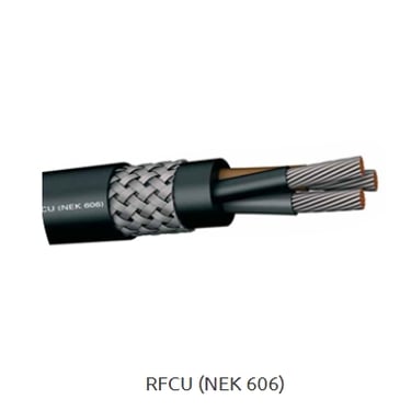
RFCU: The Standard Marine Power Cable
The standard RFCU cable represents the workhorse of marine electrical installations, designed for general shipboard applications including power distribution, control circuits, and lighting systems. This cable features a robust construction starting with electrolytic, tinned, and stranded copper conductors that comply with IEC 60228 Class 2 standards, though Class 5 flexibility is available as an option for applications requiring enhanced bendability.
The insulation system employs halogen-free Ethylene Propylene Rubber (EPR) or halogen-free High-temperature Ethylene Propylene Rubber (HEPR), providing excellent electrical properties while eliminating toxic halogen emissions during fire conditions. The conductor arrangement follows a sophisticated twisted configuration where cores are arranged in double or triple formations, with these pairs or triads then twisted concentrically to minimize electromagnetic interference and improve overall cable performance.
Each pair or triad includes a dedicated electrolytic, tinned, and twisted copper grounding wire positioned strategically to ensure effective earthing throughout the cable length. An electrolytic copper-coated polyester tape screen with 100% coverage surrounds each pair/triad and its associated ground wire, providing comprehensive electromagnetic shielding at the individual circuit level.
The cable construction incorporates a halogen-free bedding compound that secures internal components and provides additional protection, followed by a screen of braided galvanized steel wires that adds mechanical protection and supplementary electromagnetic shielding. The outer sheath utilizes SHF2 compound as standard, with SHF MUD available as an option for applications requiring enhanced resistance to drilling fluids and harsh chemical environments.
Operating at a rated voltage of 0.6/1 kV with a test voltage of 3.5 kV, the standard RFCU cable maintains reliable performance across temperature ranges from -15°C to +90°C, with extended range options down to -40°C available upon request. The minimum bending radius specification of eight times the overall cable diameter ensures installation flexibility while protecting internal components from mechanical stress.
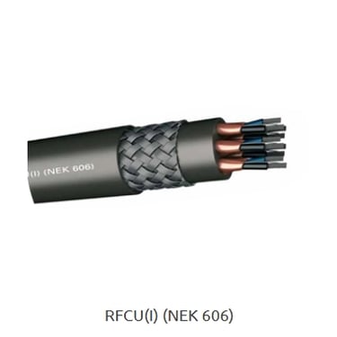
RFCU(I): Enhanced Fire Resistance for Critical Systems
The RFCU(I) variant incorporates an integrated fire-resistant layer in the form of mica tape applied directly to each conductor, transforming this cable into a specialized solution for fire-critical applications. This enhancement allows the cable to maintain circuit integrity during fire conditions, making it essential for emergency systems, fire pumps, emergency lighting, and other safety-critical applications where continued operation during fire emergencies can mean the difference between life and death.
The construction mirrors the standard RFCU cable in most respects, utilizing the same high-quality copper conductors, halogen-free insulation materials, and sophisticated twisted pair arrangements. However, the addition of mica tape separation around each conductor provides the crucial fire-resistant properties that define this variant. Mica, being a naturally occurring mineral with exceptional high-temperature stability, maintains its insulating properties even when exposed to extreme heat, allowing electrical circuits to continue functioning during fire conditions.
This fire-resistant capability comes with specific performance certifications, including compliance with IEC 60331 fire resistance standards in addition to the standard flame retardant requirements. The cable operates at a lower voltage rating of 250V with a 1.5 kV test voltage, reflecting its typical application in control and signaling circuits rather than primary power distribution.
The minimum bending radius increases to ten times the cable diameter due to the additional mica tape layer, requiring careful consideration during installation planning. Despite this constraint, the RFCU(I) variant maintains the same temperature operating range and environmental resistance as the standard version, while providing the critical fire resistance properties essential for emergency systems.
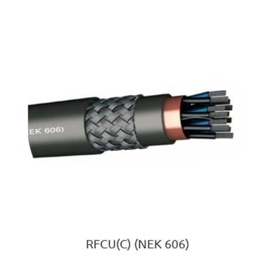
RFCU(C): Superior EMI Protection for Sensitive Systems
The RFCU(C) variant addresses the growing need for electromagnetic interference protection in modern marine electrical systems. As vessels incorporate increasingly sophisticated electronic systems including navigation equipment, communication systems, and automated control systems, the potential for electromagnetic interference between circuits becomes a significant concern. The RFCU(C) cable provides enhanced shielding specifically designed to prevent EMI issues in sensitive applications.
While maintaining the same fundamental construction principles as other RFCU variants, the RFCU(C) incorporates additional shielding measures optimized for EMI protection. The twisted pair arrangement reduces common-mode interference, while the comprehensive screening system provides superior isolation from external electromagnetic fields. This makes the cable particularly suitable for instrumentation circuits, communication systems, data transmission, and control systems where signal integrity is paramount.
The cable operates at the same 250V rating as the RFCU(I) variant, with identical temperature ranges and environmental resistance properties. The enhanced shielding does require careful attention to proper termination and grounding practices to ensure the EMI protection remains effective throughout the installation.
Comparative Analysis of RFCU Variants
When examining these three variants side by side, several key distinctions emerge that guide selection decisions. The standard RFCU cable offers the highest voltage rating at 0.6/1 kV, making it suitable for primary power distribution applications, while both RFCU(I) and RFCU(C) operate at 250V, reflecting their specialized roles in control and signaling circuits.
The bending radius requirements differ significantly, with standard RFCU allowing tighter bends at eight times diameter compared to ten times diameter for the specialized variants. This difference impacts installation planning, particularly in confined spaces where routing flexibility is limited.
Fire resistance represents the primary distinguishing feature of RFCU(I), providing circuit integrity during fire conditions that neither of the other variants can match. Conversely, the enhanced EMI protection of RFCU(C) addresses interference concerns that standard cables cannot adequately resolve.
Cost considerations typically follow a hierarchy where standard RFCU represents the most economical option, RFCU(I) commands a premium for its fire-resistant properties, and RFCU(C) represents the highest cost due to its specialized EMI protection features. Understanding these trade-offs enables informed decision-making that balances performance requirements with budget constraints.


Key Selection Criteria in Project Design
Selecting the appropriate RFCU cable variant requires systematic evaluation of multiple technical and operational factors. Each criterion contributes to the overall suitability of a particular cable type for specific applications within marine electrical systems.
Voltage Rating and System Compatibility
The voltage rating represents one of the most fundamental selection criteria, as it determines the cable's suitability for different electrical system applications. The standard RFCU cable's 0.6/1 kV rating makes it appropriate for main power distribution circuits, motor feeders, and general power applications throughout the vessel. This voltage capability aligns well with typical shipboard electrical systems that operate at 440V, 480V, or similar voltage levels commonly found in marine installations.
In contrast, the 250V rating of both RFCU(I) and RFCU(C) variants limits their application to control circuits, instrumentation systems, communication networks, and low-voltage power applications. This lower voltage rating reflects the specialized nature of these cables and their intended use in secondary systems rather than primary power distribution.
When evaluating voltage requirements, consider not only the nominal operating voltage but also the system's fault conditions and transient voltage levels. Marine electrical systems can experience significant voltage variations due to generator load changes, motor starting currents, and switching operations. The selected cable must maintain reliable insulation performance under these dynamic conditions.
Current Carrying Capacity and Conductor Sizing
Current carrying capacity depends on multiple factors including conductor cross-sectional area, ambient temperature, installation method, and grouping effects when multiple cables are installed together. The copper conductors in RFCU cables comply with IEC 60228 standards, ensuring consistent electrical properties and predictable current ratings.
Conductor sizing must account for not only the steady-state current requirements but also starting currents for motor loads, fault current levels, and voltage drop considerations over the cable length. Marine installations often involve significant cable runs from central distribution points to remote loads, making voltage drop calculations particularly important for maintaining proper equipment operation.
The availability of Class 5 stranded conductors as an option provides enhanced flexibility for applications requiring frequent movement or tight bending, though this comes at some cost premium compared to standard Class 2 conductors. The choice between conductor classes should consider the installation environment and expected mechanical stresses during both installation and operation.
Fire Safety and Emergency System Requirements
Fire safety considerations play a crucial role in marine cable selection due to the confined nature of vessels and the limited escape routes available during emergency situations. The standard RFCU cable provides excellent flame retardant properties complying with IEC 60332/1 and IEC 60332/3 Category A requirements, preventing fire propagation along cable routes under normal circumstances.
However, systems that must continue operating during fire conditions require the enhanced capabilities of RFCU(I) cables. Emergency lighting systems, fire pump controls, emergency communication systems, and critical navigation equipment fall into this category. These systems serve essential safety functions that cannot be compromised even when fire conditions exist in the cable routing areas.
The fire resistance provided by mica tape in RFCU(I) cables maintains circuit integrity for specified time periods during fire exposure, allowing emergency systems to continue functioning when they are most needed. This capability comes at a cost premium that must be weighed against the critical nature of the protected systems.
Electromagnetic Compatibility Requirements
Modern marine electrical systems incorporate numerous electronic devices that both generate and are susceptible to electromagnetic interference. Navigation systems, communication equipment, variable frequency drives, and computerized control systems all present EMI challenges that must be addressed through proper cable selection and installation practices.
The enhanced shielding provided by RFCU(C) cables offers superior protection against electromagnetic interference, making these cables essential for sensitive instrumentation circuits, data communication lines, and control systems where signal integrity is critical. The effectiveness of this shielding depends heavily on proper installation practices, particularly regarding shield termination and grounding arrangements.
Applications that do not involve sensitive electronic equipment may not require the enhanced EMI protection of RFCU(C) cables, allowing the use of standard RFCU cables with appropriate installation practices to minimize interference issues. Understanding the EMI environment and sensitivity requirements of connected equipment guides this selection decision.
Environmental and Chemical Resistance
Marine environments expose cables to various aggressive substances including saltwater, oils, cleaning chemicals, and atmospheric contaminants. The SHF2 outer sheath material provides excellent resistance to most marine environmental conditions, while the optional SHF MUD formulation offers enhanced protection against drilling fluids and specialized chemicals encountered in offshore operations.
Temperature considerations extend beyond the standard operating range to include installation conditions, storage requirements, and potential exposure to heat sources such as engine rooms or exhaust systems. The halogen-free insulation materials maintain their properties across the specified temperature range while providing superior performance during fire conditions compared to traditional halogenated compounds.
UV resistance becomes important for cables that may be exposed to sunlight during installation or in areas with significant natural lighting. While RFCU cables are primarily designed for internal installation, temporary exposure during construction and maintenance activities requires consideration of UV stability.


Cost vs Performance: Making the Right Choice
Effective cable selection requires balancing performance requirements with cost constraints to achieve optimal value for marine electrical projects. Understanding the cost hierarchy and performance trade-offs enables informed decision-making that meets technical requirements without unnecessary expense.
Understanding the Cost Hierarchy
The cost relationship between RFCU variants follows a predictable pattern based on the complexity and specialized materials required for each type. Standard RFCU cables represent the most economical option, providing excellent performance for general marine applications at the lowest material cost. The straightforward construction and use of standard materials contribute to competitive pricing that makes this variant attractive for widespread use throughout vessel electrical systems.
RFCU(I) cables command a significant premium over standard RFCU due to the addition of mica tape fire-resistant layers. The specialized mica material, additional manufacturing steps, and quality control requirements associated with fire-resistant performance contribute to higher costs. However, this premium must be evaluated against the critical nature of fire safety systems and the regulatory requirements that often mandate fire-resistant cables for specific applications.
RFCU(C) cables typically represent the highest cost option due to the enhanced shielding systems and specialized construction required for superior EMI protection. The additional materials, manufacturing complexity, and performance testing associated with electromagnetic compatibility contribute to premium pricing that reflects the specialized nature of these cables.
Strategic Cost Optimization Approaches
Effective cost management requires strategic application of different cable types based on actual requirements rather than over-specifying cables for non-critical applications. A systematic approach to cable selection can achieve significant cost savings while maintaining appropriate performance levels throughout the electrical system.
Zone-based selection strategies recognize that different areas of a vessel present varying levels of risk and performance requirements. Accommodation areas, for example, may not require the same level of fire resistance as engine rooms or electrical equipment spaces. By carefully analyzing the specific requirements for each installation zone, designers can specify appropriate cable types that provide necessary performance without unnecessary cost.
System criticality analysis helps identify which circuits truly require enhanced performance characteristics. Emergency lighting systems clearly need fire-resistant cables, while general accommodation lighting may perform adequately with standard RFCU cables. Similarly, sensitive navigation and communication circuits benefit from EMI-protected cables, while basic power distribution circuits may not require this level of protection.
Practical Application Examples
Consider a typical engine room installation where multiple cable types may be appropriate for different applications. Main power feeders for essential equipment require the robust construction and higher voltage rating of standard RFCU cables, providing reliable power distribution at economical cost. Emergency systems such as fire pumps and emergency lighting circuits justify the premium cost of RFCU(I) cables due to their critical safety functions.
Instrumentation and control circuits in the same engine room may require RFCU(C) cables to ensure reliable operation in the electrically noisy environment created by large motors, variable frequency drives, and switching equipment. The enhanced EMI protection prevents interference that could compromise control system reliability or accuracy.
In accommodation areas, standard RFCU cables typically provide appropriate performance for lighting and general power circuits at the most economical cost. Emergency lighting circuits still require RFCU(I) cables for fire safety compliance, but the majority of circuits can utilize standard cables without performance compromise.
Communication and data networks throughout the vessel benefit from RFCU(C) cables to ensure signal integrity and prevent interference from other electrical systems. The cost premium for these specialized cables is justified by the critical nature of modern vessel communication and navigation systems.
Long-term Value Considerations
While initial cable costs represent a significant project expense, long-term reliability and maintenance considerations often justify higher initial investments in appropriate cable selection. Premium cables that provide superior environmental resistance, mechanical durability, and performance characteristics typically offer better long-term value through reduced maintenance requirements and extended service life.
Fire-resistant cables, despite their higher initial cost, provide insurance against catastrophic failures that could result in vessel loss or personnel casualties. The cost of RFCU(I) cables becomes insignificant when compared to potential losses from emergency system failures during fire conditions.
Similarly, EMI-protected cables prevent interference issues that could require extensive troubleshooting, system modifications, or equipment replacement. The initial premium for RFCU(C) cables often proves economical compared to the costs associated with resolving electromagnetic compatibility problems after installation.
Installation Considerations for Long-Term Reliability
Proper installation practices are essential for achieving the designed performance and service life from RFCU cables. Even the highest quality cables will fail prematurely if installation procedures compromise their integrity or create conditions that accelerate degradation.
Pre-Installation Preparation and Storage
Cable storage and handling practices before installation significantly impact long-term reliability. RFCU cables should be stored in dry, temperature-controlled environments that protect them from moisture ingress, temperature extremes, and mechanical damage. Cable drums should be stored upright and rotated periodically to prevent permanent deformation from prolonged static loading.
Moisture control during storage and installation is particularly critical for marine applications where humidity levels are typically high. Cable ends should be sealed immediately upon cutting to prevent moisture ingress into the insulation system. Any cables that have been exposed to moisture should be thoroughly dried and tested before installation to ensure insulation integrity remains intact.
Mechanical handling during installation requires careful attention to bending radius limitations and pulling tensions. The minimum bending radius specifications for RFCU variants reflect the mechanical stress limits of the insulation and conductor systems. Exceeding these limits can cause immediate damage or create stress concentrations that lead to premature failure.
Routing and Mechanical Support Systems
Cable routing design must consider not only the electrical requirements but also the mechanical environment throughout the cable's service life. Marine vessels experience significant vibration, movement, and mechanical stresses that can fatigue cables over time if proper support and protection are not provided.
Vertical cable runs require particular attention to mechanical support systems that prevent the cable's own weight from creating excessive stress at termination points. Support spacing should follow manufacturer recommendations while considering the additional dynamic loads imposed by vessel movement and vibration.
Areas subject to high vibration levels, such as engine rooms and machinery spaces, require enhanced mechanical support systems that isolate cables from vibration sources while allowing for thermal expansion and contraction. Flexible mounting systems and adequate service loops help accommodate movement without creating mechanical stress in the cables.
Cable separation requirements become important when routing different types of circuits in close proximity. Power cables and control circuits should maintain appropriate separation distances to prevent electromagnetic interference, while fire-resistant circuits may require special routing considerations to maintain their emergency operating capabilities.
Termination and Connection Practices
Proper termination techniques are essential for maintaining the performance characteristics of RFCU cables throughout their service life. Cable glands and termination hardware must be compatible with the specific cable construction and environmental conditions at the termination location.
For RFCU(C) cables, proper shield termination and grounding practices are critical for maintaining EMI protection effectiveness. Shield continuity must be maintained through termination points while avoiding ground loops that could introduce interference or safety hazards. Proper shield grounding techniques require understanding of the overall electrical system grounding philosophy and electromagnetic compatibility requirements.
Fire-resistant cable terminations require special attention to maintain fire resistance properties through connection points. Standard termination materials may not provide adequate fire resistance, requiring specialized fire-resistant compounds or termination systems that maintain circuit integrity during fire conditions.
Testing and Commissioning Procedures
Comprehensive testing procedures verify cable installation integrity and confirm that performance specifications are met before system commissioning. Insulation resistance testing verifies that the insulation system maintains its electrical properties and has not been compromised during installation.
Continuity testing confirms proper conductor connections and verifies that grounding systems function as designed. For shielded cables, shield continuity testing ensures that EMI protection remains effective throughout the installation.
Fire-resistant cables may require specialized testing procedures to verify that fire resistance properties remain intact after installation. These tests may include partial discharge testing or other specialized techniques that confirm insulation system integrity under stress conditions.
Documentation of installation practices, test results, and system configuration provides essential information for future maintenance and troubleshooting activities. Proper documentation enables effective maintenance planning and helps ensure that future modifications maintain system integrity and performance.
Maintenance and Long-term Care
Ongoing maintenance programs help ensure continued reliable performance from RFCU cable installations throughout their service life. Regular inspection procedures should identify potential problems before they result in system failures or safety hazards.
Visual inspections can identify obvious damage, deterioration, or environmental conditions that might affect cable performance. Mechanical damage, corrosion of metallic components, or degradation of outer sheath materials may indicate the need for repairs or replacement before failure occurs.
Periodic electrical testing helps identify developing problems in insulation systems or conductor connections. Trending of test results over time can reveal gradual degradation that might not be apparent from single-point measurements.
Environmental monitoring in cable installation areas helps identify conditions that might accelerate cable aging or create reliability concerns. Temperature, humidity, and contamination levels that exceed design assumptions may require mitigation measures or accelerated replacement schedules.
Conclusion
The selection and installation of appropriate RFCU cables represents a critical decision point that influences the safety, reliability, and cost-effectiveness of marine electrical systems throughout their operational life. Understanding the distinct characteristics and applications of RFCU, RFCU(I), and RFCU(C) variants enables informed decision-making that balances performance requirements with economic constraints.
The standard RFCU cable provides robust, economical performance for general marine applications, offering excellent environmental resistance and electrical properties at competitive cost. Its higher voltage rating and flexible installation characteristics make it suitable for power distribution and general control applications throughout marine vessels and offshore installations.
RFCU(I) cables justify their cost premium through superior fire resistance properties that maintain circuit integrity during emergency conditions. These specialized cables serve essential roles in fire safety systems, emergency lighting, and other critical applications where continued operation during fire conditions can be life-saving.
RFCU(C) cables address the growing electromagnetic compatibility challenges in modern marine electrical systems. Their enhanced shielding properties ensure reliable operation of sensitive electronic systems while preventing interference issues that could compromise navigation, communication, or control system performance.
Successful implementation requires not only proper cable selection but also meticulous attention to installation practices that preserve the designed performance characteristics throughout the cable's service life. From initial storage and handling through final termination and testing, each step in the installation process contributes to long-term reliability and performance.
The investment in appropriate cable selection and professional installation practices pays dividends through reduced maintenance requirements, improved system reliability, and enhanced safety performance. In the demanding marine environment where system failures can have serious consequences, the careful selection and installation of RFCU cables represents an essential foundation for electrical system success.
By following the guidelines presented in this comprehensive guide, marine electrical professionals can make informed decisions that optimize the balance between performance, safety, compliance, and cost in their cable selection and installation practices. The result is marine electrical systems that provide reliable, safe operation throughout their design life while meeting all applicable regulatory requirements and operational needs.