
Comprehensive Guide to GYMKTY333 and GYMKTY334 Underwater Fiber Optic Cables for Marine Applications
Discover the features, technical specifications, and marine engineering applications of GYMKTY333 and GYMKTY334 underwater fiber optic cables. Learn about their structure, tensile performance, compression resistance, and suitability for offshore and subsea environments.
BLOGS
6/4/202516 min read


Introduction: The Foundation of Underwater Communication Networks
Underwater fiber optic cables represent one of the most sophisticated achievements in marine engineering and telecommunications technology. These specialized cables serve as the invisible highways that carry vast amounts of digital information across ocean floors, connecting continents and enabling the global internet infrastructure we depend upon today. Unlike their terrestrial counterparts, underwater fiber optic cables must withstand extreme environmental conditions including crushing water pressure, corrosive saltwater exposure, mechanical stress from ocean currents, and the challenging process of subsea installation.
The significance of underwater optical cables in modern communication cannot be overstated. They form the backbone of international telecommunications, carrying over 95% of all intercontinental data traffic. Beyond communication, these cables play crucial roles in marine engineering applications, including offshore oil and gas operations, underwater monitoring systems, scientific research networks, and military surveillance infrastructure.
The key performance requirements for underwater fiber optic cables encompass three fundamental characteristics that distinguish them from standard cables. First, mechanical strength must be sufficient to withstand the enormous tensile forces encountered during installation and the ongoing stresses of ocean environments. Second, flexibility remains essential to accommodate the dynamic installation process and subsequent movement caused by ocean currents and seismic activity. Third, comprehensive waterproofing ensures long-term reliability in one of the most challenging environments on Earth, where even microscopic water ingress can compromise the entire system's integrity.
Understanding Cable Classification Systems
Structural Design Categories
The classification of underwater fiber optic cables primarily depends on their structural architecture, which determines their mechanical properties and suitable applications. Two primary structural designs dominate the underwater cable industry, each optimized for specific deployment scenarios and performance requirements.

Steel Wire Armored Optical Cable Configuration
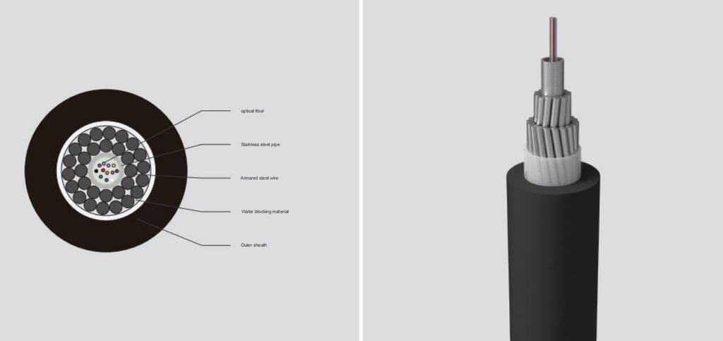
The steel wire armored optical cable represents the fundamental design approach for underwater applications. This configuration begins with optical fibers housed within a protective stainless steel tube, which serves as the primary barrier against water ingress and provides initial mechanical protection. The stainless steel tube selection proves critical, as it must resist corrosion from saltwater while maintaining structural integrity under pressure.
Surrounding this core assembly, stranded steel wires form the armoring layer, which provides the cable's primary tensile strength and crush resistance. These steel wires are carefully selected for their mechanical properties and corrosion resistance, often featuring specialized coatings or alloy compositions designed for marine environments. The armoring pattern and wire gauge directly influence the cable's performance characteristics, including its flexibility, strength, and installation behavior.
Water-blocking materials fill the spaces between components, preventing longitudinal water migration that could compromise the cable's integrity over time. These materials typically consist of specialized gels or swelling powders that expand upon contact with water, creating an effective seal. The outer sheath completes the assembly, providing the final barrier against environmental hazards while offering additional mechanical protection during handling and installation.
Inner Sheath Reinforced Armored Optical Cable Design
The inner sheath reinforced armored optical cable incorporates an additional protective layer between the core assembly and the steel wire armoring. This enhanced design provides superior protection in demanding applications where additional mechanical stress or environmental exposure is anticipated. The inner sheath typically consists of a durable polymer material that adds another level of water resistance while providing cushioning between the optical fiber assembly and the armoring.
This configuration proves particularly valuable in applications involving frequent handling, dynamic loading conditions, or extended deployment periods where enhanced reliability justifies the additional complexity and cost. The inner sheath also provides improved flexibility characteristics, which can be crucial during installation in confined spaces or around obstacles.
Application-Based Classification Systems
Understanding underwater cable applications requires examining the diverse environments and operational requirements these systems must satisfy. Each application category presents unique challenges that influence cable design and selection criteria.
Shallow Water Deployment Scenarios
Shallow water applications encompass ports, harbors, rivers, and offshore platform connections where water depths typically range from several meters to a few hundred meters. These environments present specific challenges including increased mechanical activity from vessels, anchoring operations, fishing activities, and tidal forces. Cables in shallow water face higher risks of physical damage from human activities and marine traffic, requiring robust mechanical protection and often burial beneath the seabed.
The dynamic nature of shallow water environments demands cables with excellent fatigue resistance and flexibility to accommodate constant movement from currents and waves. Temperature variations prove more significant in shallow waters, requiring materials that maintain their properties across broader temperature ranges. Additionally, the accessibility of shallow water installations enables more frequent maintenance and inspection, influencing design decisions regarding repairability and monitoring capabilities.
Deep-Sea Communication Networks
Deep-sea communication applications involve the massive submarine telecommunication cables that span ocean basins, carrying the majority of international internet traffic. These cables operate in water depths exceeding several kilometers, where pressure levels reach hundreds of atmospheres and temperatures remain consistently near freezing. The extreme environment eliminates many of the mechanical hazards found in shallow water but introduces unique challenges related to installation logistics, pressure resistance, and long-term reliability.
Deep-sea cables must maintain signal integrity over distances of thousands of kilometers while withstanding decades of continuous operation without maintenance access. The installation process itself presents enormous technical challenges, requiring specialized cable-laying vessels and precise navigation to avoid underwater obstacles and optimize the cable route for minimal stress and maximum protection.
Specialized Industrial Applications
High-pressure, high-impact underwater industrial operations require cables designed for extreme mechanical stress and harsh chemical environments. These applications include offshore oil and gas drilling operations, underwater mining activities, and subsea processing facilities where cables face exposure to drilling fluids, high-pressure water jets, and mechanical equipment vibrations.
The cables used in these environments often incorporate enhanced armoring designs, specialized outer sheaths resistant to hydrocarbon exposure, and reinforced termination systems capable of withstanding dynamic loading from floating platforms and underwater equipment. The temporary nature of many industrial applications also influences design decisions, balancing performance requirements against cost considerations for shorter deployment periods.
Military and Surveillance Networks
Undersea monitoring systems for military and surveillance applications require cables optimized for stealth, reliability, and security. These systems often involve complex networks of sensors and communication nodes that must operate undetected while providing real-time data transmission capabilities. The cables supporting these systems incorporate specialized designs to minimize electromagnetic signatures while maximizing signal security and system reliability.
Technical Parameters and Performance Specifications
Tensile Strength Characteristics
Tensile strength represents perhaps the most critical performance parameter for underwater fiber optic cables, directly determining their ability to survive the installation process and ongoing operational stresses. Understanding the distinction between short-term and operational tensile strength proves essential for proper cable selection and deployment planning.
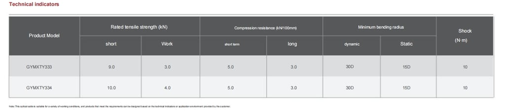
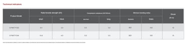
Short-term tensile strength, also known as installation tensile strength, defines the maximum load the cable can withstand during the installation process. This parameter accounts for the dynamic forces encountered during cable laying operations, including the weight of the cable itself as it descends through the water column, drag forces from ocean currents, and mechanical stresses from the installation equipment. The GYMKTY333 cable demonstrates a short-term tensile strength of 9.0 kN, while the GYMKTY334 achieves 10.0 kN, reflecting the enhanced structural design of the latter configuration.
Operational tensile strength, sometimes referred to as working tensile strength, represents the sustained load the cable can safely support during normal service conditions. This parameter ensures long-term reliability by maintaining appropriate safety margins below the cable's ultimate strength. The GYMKTY333 exhibits an operational tensile strength of 3.0 kN, while the GYMKTY334 provides 4.0 kN of working strength. These values reflect conservative design approaches that prioritize long-term reliability over maximum short-term capability.
The relationship between short-term and operational tensile strength typically involves safety factors of three to four, ensuring that normal operational loads remain well below levels that could compromise the cable's structural integrity. This conservative approach proves essential in underwater applications where cable failure can result in massive service disruptions and extremely expensive recovery operations.
Compression Resistance Properties
Compression resistance measures the cable's ability to withstand crushing forces perpendicular to its longitudinal axis, a critical parameter for cables that may be buried beneath the seabed or subjected to external loading from underwater equipment or debris. The measurement standard typically expresses compression resistance in kilonewtons per 100 millimeters of cable width, providing a normalized comparison across different cable diameters and designs.
Both GYMKTY333 and GYMKTY334 cables demonstrate identical compression resistance characteristics, with short-term values of 5.0 kN per 100 mm and long-term ratings of 3.0 kN per 100 mm. The short-term compression resistance addresses temporary loading conditions that might occur during installation or accidental contact with heavy objects. The long-term compression resistance ensures the cable can withstand sustained loading from burial beneath sediment layers or permanent installation beneath structures.
The significance of compression resistance extends beyond simple mechanical protection to include considerations of signal integrity and long-term reliability. Excessive compression can alter the optical fiber's geometry, potentially affecting signal transmission characteristics or creating stress concentrations that lead to premature failure. The conservative long-term ratings ensure that normal burial and operational loading conditions will not compromise the cable's optical performance over its intended service life.
Bending Radius Specifications
Bending radius limitations define the minimum curvature the cable can accommodate without risking damage to the optical fibers or structural components. These specifications typically distinguish between dynamic bending conditions, where the cable experiences repeated flexing, and static bending situations involving permanent installation curves.
The dynamic bending radius, typically specified as 30 times the cable diameter (30D), accounts for the fatigue stresses associated with repeated flexing during installation and operation. This parameter proves critical during the cable laying process, where the cable must navigate around obstacles, accommodate vessel movements, and conform to seabed topography. The relatively large dynamic bending radius ensures that the optical fibers remain within their elastic limits, preventing microbending losses or physical damage.
Static bending radius specifications, usually set at 15 times the cable diameter (15D), apply to permanent installation configurations where the cable remains in a fixed curved position. The reduced static bending radius reflects the absence of fatigue considerations while still maintaining adequate safety margins for the optical fiber performance. Understanding these limitations proves essential for route planning and installation procedures, particularly in confined spaces or areas with complex underwater topography.
The bending radius requirements directly influence installation procedures and equipment selection. Cable laying vessels must be equipped with handling systems that maintain appropriate bend radii throughout the deployment process, while underwater trenching and burial operations must account for these limitations when navigating obstacles or creating protective curves.
Impact Resistance Capabilities
Impact resistance measures the cable's ability to withstand sudden mechanical shocks, such as those caused by dropping objects, anchor strikes, or collision with underwater vehicles. Both GYMKTY333 and GYMKTY334 cables demonstrate impact resistance ratings of 10 N·m, indicating their ability to absorb significant shock loads without compromising their structural integrity or signal transmission capabilities.
The impact resistance specification becomes particularly important in shallow water applications where cable exposure to mechanical hazards is more likely. Fishing activities, anchor dragging, and construction operations all present potential impact threats that the cable must withstand. The 10 N·m rating reflects a robust design capable of surviving reasonable impact scenarios while maintaining operational capability.
Impact resistance also influences cable installation procedures, particularly during the deployment phase when cables may contact the seabed, underwater structures, or installation equipment. The specified impact resistance provides confidence that normal installation activities will not compromise the cable's integrity, reducing the risk of installation-related failures that could prove extremely costly to remedy.
Core Components and Material Engineering
Optical Fiber Assembly
The optical fiber serves as the fundamental signal transmission element within underwater cables, carrying light pulses that encode digital information across vast distances. These fibers, typically measuring 125 micrometers in diameter, must maintain their optical properties despite the mechanical stresses and environmental conditions encountered in underwater applications.
The optical fiber selection for underwater cables typically emphasizes low attenuation characteristics to maximize transmission distances and minimize the need for signal regeneration equipment. Standard single-mode fibers operating in the 1550-nanometer wavelength region provide optimal performance for long-distance submarine applications, while multimode fibers may be suitable for shorter-distance applications where higher signal capacity is required.
Protection of the optical fiber within the cable assembly proves critical to maintaining signal integrity and preventing physical damage. The fibers are typically housed within protective tubes or surrounded by gel-filled spaces that provide cushioning against mechanical stress while preventing water ingress that could affect the optical properties.
Stainless Steel Tube Protection
The stainless steel tube surrounding the optical fiber assembly provides the primary barrier against water ingress while offering substantial mechanical protection. The selection of stainless steel for this application reflects its excellent corrosion resistance in saltwater environments combined with sufficient mechanical strength to protect the delicate optical fibers.
The stainless steel tube design must balance several competing requirements. Wall thickness must be sufficient to provide mechanical protection and pressure resistance while remaining thin enough to minimize the overall cable diameter and maintain flexibility. The tube's internal environment typically contains dry gases or specialized gels that prevent moisture accumulation and maintain optimal conditions for the optical fibers.
Manufacturing quality of the stainless steel tube proves critical to long-term cable reliability. Seamless construction eliminates potential weak points where corrosion or mechanical failure might initiate, while precise dimensional control ensures proper fit with other cable components. Surface treatments or specialized alloy compositions may be employed to enhance corrosion resistance or improve bonding with adjacent materials.
Steel Wire Armoring Systems
The steel wire armoring provides the cable's primary mechanical strength, enabling it to withstand the enormous forces encountered during installation and operation. The armoring design typically employs multiple layers of high-strength steel wires arranged in helical patterns that distribute loads evenly while maintaining cable flexibility.
Wire selection for underwater cable armoring involves careful consideration of strength, corrosion resistance, and fatigue properties. High-carbon steel wires provide maximum strength but may require protective coatings or treatments to prevent corrosion in saltwater environments. Stainless steel wires offer superior corrosion resistance but may have lower ultimate strength, requiring larger wire diameters or additional layers to achieve equivalent mechanical performance.
The armoring pattern significantly influences cable properties, with the lay angle of the helical wires affecting the balance between tensile strength, flexibility, and torsional stability. Contra-helical armoring, where adjacent layers are wound in opposite directions, provides excellent torsional balance and prevents the cable from twisting during installation and handling.
Water-Blocking Material Systems
Water-blocking materials serve as the cable's defense against longitudinal water migration, preventing moisture from traveling along the cable length and potentially compromising multiple sections if the outer sheath is breached. These materials must function effectively in saltwater environments while remaining stable over the cable's intended service life.
Traditional water-blocking gels provide excellent sealing properties and can flow to fill voids as the cable flexes during installation and operation. However, these gels must maintain their properties across the wide temperature range encountered in underwater applications, from near-freezing deep-sea conditions to elevated temperatures that may occur during installation or in shallow water environments.
Modern water-blocking systems often employ super-absorbent polymers that swell dramatically when exposed to water, creating effective barriers against moisture ingress. These systems offer advantages in terms of storage stability and handling convenience while providing superior long-term blocking performance. The selection between gel and powder systems often depends on specific application requirements and manufacturing considerations.
Outer Jacket Design and Materials
The outer jacket serves as the cable's final defense against environmental hazards while providing mechanical protection during handling and installation. Material selection for the outer jacket must consider resistance to saltwater corrosion, ultraviolet radiation, abrasion, and the wide range of temperatures encountered in marine environments.
Polyethylene compounds represent the most common choice for underwater cable jackets, offering excellent chemical resistance, low water absorption, and good mechanical properties. Cross-linked polyethylene provides enhanced temperature and stress-crack resistance, making it suitable for demanding applications where elevated temperatures or mechanical stress are anticipated.
The jacket thickness must be optimized to provide adequate protection while minimizing cable diameter and weight. Thicker jackets offer superior mechanical protection but increase installation complexity and cost, while thinner jackets reduce material costs but may be more susceptible to damage during handling and installation.


Engineering and Installation Considerations
Cable Laying Methodologies
The deployment of underwater fiber optic cables requires sophisticated engineering approaches that account for the unique challenges of the marine environment. Cable laying methodologies vary significantly depending on water depth, seabed conditions, environmental factors, and the specific requirements of the installation.
Surface laying represents the most straightforward deployment method, where cables are laid directly onto the seabed without burial or additional protection. This approach proves suitable for deep-water applications where the risk of mechanical damage is minimal and the seabed provides stable support. The cable route must be carefully surveyed to avoid obstacles, steep slopes, or areas of seismic activity that could compromise the installation.
Trenching and burial methods provide enhanced protection for cables in shallow water or areas with high levels of marine activity. Specialized trenching equipment creates a channel in the seabed into which the cable is laid before being covered with sediment or protective materials. The burial depth typically ranges from one to three meters, depending on local conditions and protection requirements.
Post-lay burial techniques employ remotely operated vehicles or specialized burial equipment to create protective trenches after the cable has been surface-laid. This approach allows for more precise cable placement and can accommodate complex seabed topography that might be difficult to navigate during simultaneous laying and burial operations.
Mechanical Loading Analysis
Understanding the mechanical loads imposed on underwater cables during installation and operation is essential for ensuring long-term reliability and preventing premature failure. The analysis of these loads requires consideration of both static forces, such as the cable's own weight and seabed contact pressure, and dynamic forces resulting from ocean currents, vessel movements, and installation equipment operation.
During the installation process, the cable experiences its maximum mechanical stress as it pays out from the cable-laying vessel and descends through the water column. The combination of the cable's weight, drag forces from ocean currents, and tension applied by the laying equipment creates complex stress patterns that must remain within the cable's design limits throughout the installation process.
Operational loading conditions involve the long-term forces that the cable must withstand throughout its service life. These include the gravitational loads from the cable's own weight, pressure forces from the overlying water column, and dynamic loads from ocean currents and seismic activity. The cable design must ensure that these operational loads remain well below the cable's ultimate strength to provide adequate safety margins.
Environmental Adaptation Requirements
The marine environment presents numerous challenges that underwater cables must overcome to achieve reliable long-term operation. Temperature variations, from near-freezing deep-sea conditions to elevated temperatures in shallow tropical waters, require materials and designs that maintain their properties across this range.
Salinity effects prove particularly challenging for cable materials, as saltwater provides a highly corrosive environment that can degrade metallic components and affect the properties of polymer materials. The cable design must incorporate appropriate material selections and protective measures to ensure that corrosion does not compromise the cable's integrity over its intended service life.
Biofouling represents another environmental challenge, particularly in shallow water applications where marine organisms may attach to the cable and affect its properties or create additional loading conditions. While biofouling rarely threatens the cable's structural integrity directly, it can complicate maintenance operations and may contribute to increased drag forces in areas with strong currents.
Industry Standards and Testing Protocols
The underwater cable industry operates under strict standards and testing protocols that ensure consistent quality and reliability across different manufacturers and applications. These standards address everything from material specifications and manufacturing processes to testing procedures and installation requirements.
International Electrotechnical Commission standards provide comprehensive guidelines for underwater cable design, testing, and installation. These standards specify minimum performance requirements for mechanical properties, environmental resistance, and signal transmission characteristics while establishing standardized testing procedures that enable reliable comparison between different cable designs.
International Telecommunication Union recommendations address the specific requirements for submarine telecommunication cables, including standards for signal transmission performance, system reliability, and maintenance procedures. These recommendations prove particularly important for cables that must interface with international telecommunication networks and maintain compatibility with equipment from multiple manufacturers.
Testing protocols for underwater cables encompass comprehensive mechanical, environmental, and electrical evaluations that validate the cable's performance under simulated operating conditions. Tensile strength testing verifies the cable's ability to withstand installation and operational loads, while compression testing confirms its resistance to crushing forces. Flexibility testing ensures that the cable can accommodate the bending requirements of installation and operation without compromising its integrity.
Environmental testing subjects cables to accelerated aging conditions that simulate the effects of long-term exposure to saltwater, temperature cycling, and ultraviolet radiation. These tests provide confidence in the cable's long-term reliability and help identify potential failure modes that might not be apparent from short-term testing.
Future Developments and Emerging Technologies
The underwater cable industry continues to evolve, driven by increasing demands for data capacity, improved reliability, and enhanced functionality. Smart cable technologies represent one of the most significant developments, incorporating sensors and monitoring systems that provide real-time information about cable condition and environmental parameters.
Integrated sensor systems can monitor cable temperature, strain, and vibration, providing early warning of potential problems and enabling predictive maintenance strategies that reduce the risk of unexpected failures. These systems also offer valuable scientific data about ocean conditions, supporting marine research and environmental monitoring efforts.
Hybrid cable designs that combine fiber optic communication capabilities with power transmission represent another important development area. These cables can provide both communication and electrical power to remote underwater installations, reducing the complexity and cost of offshore infrastructure projects.
Sustainability considerations increasingly influence cable design and manufacturing decisions, with emphasis on recyclable materials, reduced environmental impact during installation, and improved energy efficiency in manufacturing processes. These trends reflect growing awareness of environmental responsibilities and the need for sustainable technology solutions.
Advanced materials research continues to develop new compounds and composites that offer improved performance characteristics for underwater applications. These materials may provide enhanced strength-to-weight ratios, superior corrosion resistance, or improved flexibility while maintaining the reliability and durability required for underwater service.
Conclusion
Underwater fiber optic cables GYMKTY333 and GYMKTY334 represent sophisticated engineering solutions that enable reliable communication in one of Earth's most challenging environments. Their design reflects decades of accumulated knowledge about marine engineering, materials science, and optical communication systems, resulting in products capable of providing decades of reliable service in conditions that would quickly destroy conventional cables.
The comprehensive analysis of these cable types reveals the complexity involved in creating systems that can withstand the enormous mechanical forces, corrosive environment, and extreme conditions found in underwater applications. From the carefully selected optical fibers at their core to the robust outer jackets that protect against environmental hazards, every component serves a critical role in ensuring overall system reliability.
The technical parameters discussed, including tensile strength ratings of 9.0 kN and 10.0 kN for short-term loading and operational capacities of 3.0 kN and 4.0 kN respectively, demonstrate the conservative design approaches necessary for underwater applications. These specifications, combined with compression resistance ratings of 5.0 kN per 100 mm and impact resistance capabilities of 10 N·m, provide the mechanical performance necessary for successful deployment and long-term operation.
Understanding the applications for these cables, from shallow water installations supporting offshore platforms to deep-sea communication networks spanning ocean basins, illustrates their critical role in modern infrastructure. As global communications become increasingly dependent on underwater cable systems, the reliability and performance of cables like GYMKTY333 and GYMKTY334 become ever more crucial to maintaining the connectivity that supports international commerce, scientific research, and social communication.
The future of underwater fiber optic cables promises continued evolution toward smarter, more capable systems that not only provide communication capabilities but also serve as platforms for ocean monitoring and scientific research. As these technologies develop, the fundamental engineering principles demonstrated in current designs will continue to provide the foundation for increasingly sophisticated underwater communication systems that connect our world across the vast expanses of the ocean.