
BFOU Cable Selection Guide: How to Choose Between P5, P12, i+c, S3/S7, and S4/S8?
Comprehensive guide to selecting the right BFOU cables for offshore applications. Learn the differences between P5, P12, i+c, S3/S7, and S4/S8 specifications for optimal safety and performance in marine environments.
BLOGS
6/3/202512 min read


Introduction
In the demanding world of offshore installations, marine vessels, and oil & gas platforms, the selection of appropriate electrical cables can mean the difference between operational success and catastrophic failure. BFOU cables represent a specialized category of fire-resistant, halogen-free cables designed specifically for these challenging environments where safety, reliability, and environmental compliance are paramount concerns.
The complexity of modern offshore operations requires electrical systems that can withstand extreme conditions while maintaining critical functionality during emergencies. Whether powering essential navigation systems, controlling safety mechanisms, or transmitting vital instrumentation data, the cables that form the nervous system of these installations must be carefully selected based on their specific performance characteristics and environmental resistances.
This comprehensive guide aims to demystify the various BFOU cable specifications, particularly focusing on the distinctions between P5 and P12 fire resistance ratings, the integrated instrumentation and control capabilities of i+c variants, and the environmental protection levels offered by S3/S7 mud resistance and S4/S8 oil resistance classifications. Understanding these specifications is crucial for engineers, project managers, and procurement specialists who must ensure their cable selections meet both regulatory requirements and operational demands.
What Are BFOU Cables?
BFOU cables represent a sophisticated engineering solution designed to address the unique challenges of offshore electrical installations. The acronym itself reflects the cable's fundamental characteristics: these are flame-retardant, halogen-free cables specifically engineered for offshore power distribution and control applications. Unlike conventional building cables, BFOU cables must simultaneously address multiple critical performance requirements that are essential for marine and offshore safety.
The foundation of BFOU cable design lies in their compliance with rigorous international standards, primarily IEC 60092 series for electrical installations in ships, and NEK TS 606 specifications that address the specific needs of offshore installations. These standards ensure that the cables can maintain their integrity and functionality under the extreme conditions commonly encountered in marine environments, including exposure to saltwater, temperature fluctuations, mechanical stress, and potential fire hazards.
The construction of BFOU cables incorporates several key safety features that distinguish them from standard industrial cables. The conductors utilize electrolytic, stranded, tinned copper wire meeting IEC 60228 Class 2 specifications, which provides excellent conductivity while resisting corrosion in marine environments. The critical separator layer consists of mica tape applied over the conductor, which serves as a crucial fire barrier that maintains circuit integrity even when the cable is exposed to extreme temperatures.
The insulation system employs halogen-free EPR (Ethylene Propylene Rubber) or halogen-free HEPR (Hard Ethylene Propylene Rubber) compounds. This choice is particularly significant because traditional PVC insulations release toxic and corrosive gases when burned, which can be fatal in the confined spaces typical of ships and offshore platforms. The halogen-free formulation ensures that even if the cable is exposed to fire, it will not contribute to the production of toxic gases that could endanger personnel during evacuation procedures.
The screening system in BFOU cables typically consists of electrolytic, tinned copper braided screens with 90% coverage, providing excellent electromagnetic interference protection while maintaining flexibility for installation. This screening is essential in offshore environments where sensitive instrumentation and communication systems must operate reliably despite the presence of high-power electrical equipment and potentially harsh electromagnetic environments.
Key Specification Indicators in BFOU Models
Understanding the suffix designations in BFOU cable part numbers is essential for proper cable selection, as each designation corresponds to specific performance characteristics that directly impact the cable's suitability for different applications. These suffixes are not arbitrary marketing terms but represent measurable performance standards that have been developed through extensive testing and real-world experience in offshore environments.
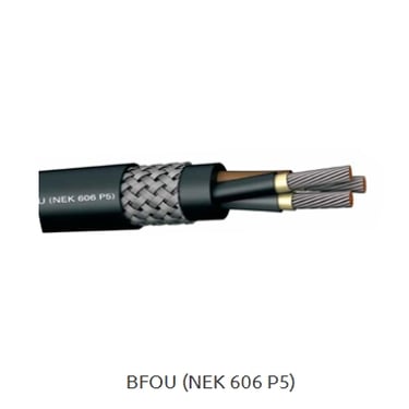
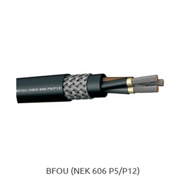
The P5 and P12 designations refer to fire resistance duration capabilities, representing one of the most critical safety parameters in offshore cable selection. P5 indicates that the cable can maintain circuit integrity for a minimum of 90 minutes when exposed to standard fire test conditions as defined by IEC 60331. This performance level is typically sufficient for general power distribution circuits where personnel evacuation can be completed within this timeframe. The P12 designation indicates enhanced fire resistance, with the cable maintaining functionality for at least 180 minutes under the same test conditions. This extended performance is crucial for circuits that must continue operating during extended emergency situations, such as emergency lighting systems, fire pump controls, and critical communication circuits.
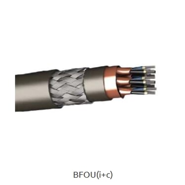
The i+c designation indicates integrated instrumentation and control functionality, representing a specialized cable design that combines power conductors with dedicated signal transmission capabilities. These cables are engineered to handle both the power requirements of field devices and the low-level signals used for process monitoring and control. The construction typically includes individual screening for each signal pair or triad, along with drain wires to ensure signal integrity in electrically noisy environments.
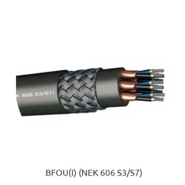
The S3 and S7 classifications address mud resistance capabilities, which is particularly relevant in drilling operations and offshore platforms where drilling mud exposure is inevitable. S3 represents basic mud resistance suitable for areas with limited exposure to water-based drilling fluids, while S7 indicates enhanced resistance capable of withstanding prolonged exposure to synthetic-based and oil-based drilling muds. This distinction is crucial because different drilling mud types have varying chemical compositions that can degrade cable materials over time.
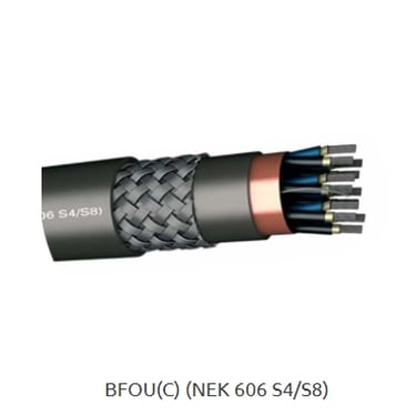
Similarly, the S4 and S8 designations indicate oil resistance levels, with S4 providing moderate protection suitable for general offshore environments and S8 offering enhanced protection for installations in areas with significant hydrocarbon exposure. The difference between these ratings can be critical in areas such as engine rooms, fuel handling systems, and processing facilities where cable exposure to oils and petroleum products is common.
Fire Resistance: Choosing Between P5 and P12
The selection between P5 and P12 fire resistance ratings represents one of the most critical decision points in offshore cable specification, as this choice directly impacts personnel safety and system survivability during emergency situations. The fundamental principle underlying fire resistance in cables is the concept of circuit integrity maintenance, which ensures that critical electrical circuits continue to function even when exposed to fire conditions.
P5 rated cables are designed to maintain their electrical performance for 90 minutes when subjected to the standardized fire test conditions specified in IEC 60331. During this test, the cable is exposed to flames at temperatures reaching 750°C while maintaining a specified voltage, and the cable must continue to conduct electricity without significant degradation. This performance level is generally adequate for circuits where the primary concern is providing sufficient time for personnel evacuation and initial emergency response actions.
The applications best suited for P5 cables include general lighting circuits, standard power distribution, and non-critical control systems where temporary loss of function would not immediately threaten life safety. In these applications, the 90-minute fire resistance provides sufficient time for emergency procedures while maintaining cost-effectiveness in the overall installation.
P12 rated cables extend this fire resistance performance to 180 minutes, representing a significant enhancement in emergency survivability. This extended performance is achieved through more robust insulation systems, enhanced mica tape barriers, and carefully engineered conductor configurations that maintain integrity under prolonged thermal stress. The additional cost and installation complexity of P12 cables is justified in applications where extended emergency operation is essential for personnel safety and asset protection.
Critical applications requiring P12 fire resistance include emergency lighting systems that must illuminate escape routes throughout extended evacuation procedures, fire pump control circuits that may need to operate for hours during firefighting operations, and communication systems that emergency responders depend upon for coordination during extended incidents. Additionally, circuits serving essential safety systems such as emergency power generation controls, fire detection and alarm systems, and critical ventilation controls typically specify P12 performance to ensure continued operation throughout emergency scenarios.
The certification process for both P5 and P12 cables involves rigorous testing procedures that simulate real-world fire conditions while monitoring electrical performance parameters. These tests are conducted by accredited laboratories and must be repeated regularly to maintain certification validity. The testing protocol includes not only the fire exposure phase but also mechanical stress testing during the fire exposure to simulate the physical stresses that cables experience in actual installations.
Control and Instrumentation: When to Choose i+c
The integrated instrumentation and control functionality represented by the i+c designation addresses the growing complexity of modern offshore installations, where sophisticated monitoring and control systems are essential for safe and efficient operations. These specialized cables represent an engineering solution that consolidates multiple circuit types into a single cable assembly, reducing installation complexity while improving system reliability and performance.
The fundamental advantage of i+c cables lies in their ability to serve dual functions within a single cable construction. The power conductors provide the electrical energy required to operate field devices such as transmitters, analyzers, and actuators, while the integrated signal pairs handle the low-level analog and digital communications required for process monitoring and control. This integration eliminates the need for separate power and signal cables, reducing both material costs and installation labor while improving system organization and maintenance accessibility.
The construction of i+c cables incorporates sophisticated screening techniques to ensure signal integrity despite the presence of power conductors within the same cable assembly. Individual screening for each signal pair or triad prevents crosstalk and electromagnetic interference, while drain wires provide effective grounding paths that maintain signal quality even in electrically noisy offshore environments. The screening materials typically consist of electrolytic copper-backed polyester tape with 100% coverage, providing comprehensive protection against external interference sources.
Applications particularly well-suited for i+c cables include distributed control systems where numerous field devices require both power and communication connections, safety instrumented systems where signal integrity is critical for protective functions, and process monitoring networks where multiple sensors and transmitters must communicate with central control systems. The integration of power and signal functions in these applications significantly simplifies cable routing and termination while reducing the potential for installation errors.
The benefits of choosing i+c cables extend beyond simple installation convenience to include improved system reliability and reduced maintenance requirements. By consolidating multiple circuit functions into fewer cable assemblies, the total number of connections and potential failure points is reduced. Additionally, the specialized construction techniques used in i+c cables often result in enhanced durability and environmental resistance compared to separate power and signal cables.
However, the selection of i+c cables requires careful consideration of system design parameters, including signal levels, power requirements, and electromagnetic compatibility requirements. The integration of power and signal circuits within a single cable assembly requires proper design coordination to ensure that power conductor sizing is adequate for the connected loads while signal pair characteristics meet the requirements of the communication protocols being used.
Environmental Resistance: S3 vs. S7 and S4 vs. S8
The harsh environmental conditions encountered in offshore installations demand cables with specialized resistance characteristics that go far beyond the requirements of typical industrial applications. The S3/S7 mud resistance and S4/S8 oil resistance classifications represent carefully engineered material formulations and construction techniques designed to maintain cable integrity despite prolonged exposure to aggressive chemical environments.
Understanding mud resistance classifications requires knowledge of the different types of drilling fluids used in offshore operations and their varying chemical compositions. Water-based drilling muds, which represent the simplest formulation, consist primarily of water, clay, and various additives designed to control density and viscosity. These fluids are generally less aggressive toward cable materials, making S3 mud resistance adequate for areas with limited exposure or where water-based muds are predominantly used.
Synthetic-based and oil-based drilling muds present significantly greater challenges for cable materials due to their complex chemical compositions and higher penetration capabilities. These advanced drilling fluids often contain surfactants, emulsifiers, and other chemical additives that can penetrate cable sheaths and attack insulation materials over time. S7 mud resistance provides enhanced protection against these more aggressive formulations through specialized compound formulations and improved barrier properties.
The practical implications of mud resistance selection become apparent when considering the long-term reliability requirements of offshore installations. Cables with inadequate mud resistance may experience gradual degradation of their insulation properties, leading to reduced dielectric strength and eventual failure. In critical applications, such failures can result in equipment damage, production interruptions, and potential safety hazards.
Oil resistance classifications address the challenge of hydrocarbon exposure, which is inevitable in offshore oil and gas operations. S4 oil resistance provides adequate protection for general offshore environments where occasional exposure to petroleum products may occur, such as in equipment rooms or general platform areas. The cable compounds used in S4 ratings are formulated to resist swelling and degradation when exposed to typical petroleum products for limited durations.
S8 oil resistance represents enhanced protection designed for installations in areas with significant and prolonged hydrocarbon exposure. These areas include engine rooms where fuel and lubricating oil exposure is common, fuel handling systems where spillage may occur, and processing facilities where hydrocarbon vapors and liquids are regularly present. The compound formulations used in S8 rated cables incorporate specialized plasticizers and polymer matrices that maintain their physical and electrical properties despite prolonged hydrocarbon exposure.
The selection between these resistance levels requires careful analysis of the specific environmental conditions expected in each installation area. Factors to consider include the types of fluids present, the frequency and duration of exposure, the ambient temperature conditions that may accelerate chemical reactions, and the consequences of cable failure in each specific application.


Application Scenarios and Selection Guidelines
The practical application of BFOU cable selection principles becomes clearest when examining specific installation scenarios that commonly occur in offshore environments. Each scenario presents unique combinations of safety requirements, environmental challenges, and performance expectations that must be carefully matched with appropriate cable specifications.
Consider a fire-critical control room scenario where the electrical systems must continue operating throughout extended emergency situations while being exposed to both drilling mud environments and potential hydrocarbon vapors. In this application, the recommended specification would be BFOU(i+c) P12 S7 S8, which provides integrated instrumentation and control functionality with 180-minute fire resistance and enhanced protection against both mud and oil exposure. The integrated i+c functionality consolidates the numerous power and signal circuits required for control room operations, while the P12 fire resistance ensures continued operation throughout extended emergency scenarios. The S7 and S8 environmental resistances provide comprehensive protection against the aggressive chemical environments typical of offshore drilling platforms.
A standard offshore lighting circuit presents different requirements where basic fire protection and moderate environmental resistance are adequate for safe operation. In this scenario, BFOU P5 S3 S4 would typically provide appropriate performance while maintaining cost-effectiveness. The P5 fire resistance provides sufficient emergency operation time for personnel evacuation, while the S3 and S4 environmental resistances offer adequate protection for lighting circuits that are not exposed to the most aggressive chemical environments.
Instrumentation installations in hazardous areas represent another critical application where comprehensive protection is essential for both safety and reliability. These installations typically require BFOU(i+c) P12 S7 S8 specifications to address the combination of fire hazards, explosive atmospheres, and aggressive chemical exposures that characterize hazardous area classifications. The integrated instrumentation functionality is particularly valuable in these applications where signal integrity is critical for safety system operation.
The decision-making process for cable selection should consider several key factors beyond the basic application requirements. Circuit criticality assessment involves evaluating the consequences of cable failure on overall system operation and personnel safety. Circuits that are essential for life safety, emergency response, or critical process control require enhanced fire resistance and environmental protection compared to general utility circuits.
Ambient hazard evaluation requires detailed analysis of the specific environmental conditions in each installation area, including the types of chemicals present, the frequency and duration of exposure, and the potential for mechanical damage or thermal stress. Installation method considerations include the routing path, accessibility for maintenance, and the mechanical stresses that cables will experience during installation and operation.
The economic aspects of cable selection must also be balanced against performance requirements, as higher-specification cables involve increased material costs and may require specialized installation techniques. However, the long-term costs associated with cable replacement, system downtime, and potential safety incidents often justify the initial investment in appropriately specified cables.
Summary: Decision Flowchart Approach
The complexity of BFOU cable selection can be significantly simplified through a systematic decision-making approach that prioritizes the most critical performance parameters based on specific application requirements. This methodology ensures that engineers can efficiently navigate the various specification options while maintaining focus on the factors that most significantly impact safety and performance.
The decision process should begin with fire rating assessment, as this parameter directly impacts personnel safety and regulatory compliance. Applications requiring extended emergency operation, such as escape route lighting, emergency communication systems, and critical safety controls, necessitate P12 fire resistance. General power distribution and non-critical control circuits can typically utilize P5 fire resistance while maintaining adequate safety margins.
Control integration requirements represent the next critical decision point, where the need for combined power and signal transmission capabilities determines whether i+c functionality is necessary. Applications with numerous field devices requiring both power and communication connections benefit significantly from integrated cables, while simple power distribution circuits may not require this functionality.
Environmental resistance selection requires careful evaluation of the specific chemical exposures expected in each installation area. High-exposure environments such as drilling areas, engine rooms, and processing facilities typically require S7 mud resistance and S8 oil resistance, while general platform areas may be adequately served by S3 and S4 resistance levels.
The most decisive parameters in cable selection are typically fire rating for safety-critical circuits, control integration for complex instrumentation systems, and environmental resistance for chemically aggressive environments. Secondary considerations include mechanical requirements such as bending radius limitations, voltage ratings, and specific regulatory requirements that may apply to particular installation types or geographical regions.
Conclusion
The selection of appropriate BFOU cables represents a critical engineering decision that directly impacts the safety, reliability, and operational effectiveness of offshore electrical installations. The various specification options available within the BFOU cable family provide engineers with the flexibility to match cable performance characteristics precisely with application requirements, ensuring optimal system performance while maintaining cost-effectiveness.
The systematic approach to cable selection outlined in this guide emphasizes the importance of understanding the relationship between cable specifications and real-world performance requirements. By carefully evaluating fire resistance needs, control integration requirements, and environmental protection necessities, engineers can make informed decisions that enhance both immediate operational performance and long-term system reliability.
The investment in properly specified BFOU cables pays dividends throughout the operational life of offshore installations through reduced maintenance requirements, enhanced safety performance, and improved regulatory compliance. As offshore operations continue to evolve toward greater complexity and higher safety standards, the importance of thoughtful cable selection will only continue to grow.
For project-specific applications, particularly those involving unique environmental conditions or specialized regulatory requirements, consultation with cable manufacturers and relevant classification societies remains essential. These technical resources can provide valuable guidance on emerging standards, specialized testing requirements, and innovative cable technologies that may offer enhanced performance for specific applications. The collaborative approach between project engineers, cable manufacturers, and regulatory bodies ensures that cable selections meet both current requirements and anticipated future needs, contributing to the overall success and safety of offshore operations.
